Saturday, April 28, 2012

FIRST DIVISION

Divide & Repeat is a new  Revit 2013 feature in the Conceptual Design Environment.  I got around to trying this one out last weekend.  Most of what I did could have been handled using a divided surface and nesting components into a curtain panel by pattern, but the new method is more direct and easier to use. 


You can draw a circle, divide it, and control the number of nodes with a parameter.  Add a radius parameter.  Then repeat on a second level.


Attach a simple adaptive component to two of the points and press the Repeat button.  You got a ring of columns.  On top of the columns I built a variable dome made from three circles whose sizes can be independently varied. The middle circle is centred between the other two as the height is varied. Allows for all kinds of shapes from onions to gherkins.


The adpative column uses a circular mass profile.  New mass family.  Draw a circle, turn the radius into a real dimension, label it, load it into another mass.  Now it's available as a profile to make things out of and it's easily locked in place. 


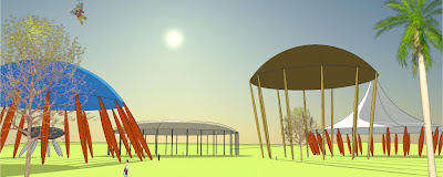
Couldn't resist playing with the new visual styles features.  Realistic view with sky background & RPC content.  Thanks to Luke for pointing out that you can see the sun if you look in the right direction.  I had this eerie feeling that I was in a Rupert Bear world from 1960 ... something about the colours I think.


If you connect more than one object to your arrays of nodes, Revit will try to interpret this as the beginning of a pattern.  So when you press the repeat button be prepared for surprise effects as the programme tries to read your mind.  But meanwhile I was busy doing a couple of roof-by-face experiments.


Wasn't too hard to get a series of triangles going, and suddenly I was in 1960 again, but this time at the Rome Olympics where Mr Nervi did his thing and produced what we all thought were incredibly free-form organic structures at the time. 


As I was doing this I had just done my exploration of Parts, and was considering calling it "a man of many parts" ... hence the quote attached to a completely irrelevant image of a chinese hat roof made of clay tiles.


Interlude where I played with images and refreshed my memory of the works of Pier Luigi Nervi.  Lots of Sport & Bridges with the odd church thrown in for good luck.


So after a bit more playing with my bulging columns I decided to try making a Y shaped support a la Palazzetto dello Sport.  Has to be adaptive of course, based on 3 points.  I linked them together in a rig, with a triangle to form a plane and a parameter to vary the position of the fork. 


Loading this in as lines and repeating it everything was fine.


So I fleshed it out with more circular profiles hosted on points.  Hosted the circles while the points were away from the end, then pushed them out to the end using the normalised curve parameter.


So I had a highly parametric family, (roughly analogous to Nervi's dome on Y supports) which could be used to explore variations in the number of supports, curvature of the dome, etc.  In short an "early design tool"


Once you've made one, further iterations become progressively easier.  Triangular supports for example, and divided surface domes.  I ran out of time at this point, having barely scratched the surface.  There is the beginnings of a kit of parts here that could be fitted together & reused in all kinds of ways. 


Had to end with another "realistic" shot, complete with Dwayne at his usual moody best.  Rupert seems to have sneaked back in as well, and check out the free entourage I downloaded from a link that Luke Johnson shared (see post)  One of the ladies is looking mighty suspiciously at Dwayne ... but really, can you blame her ?

Thursday, April 26, 2012

MORE PUNISHMENT

Second day of punishment on AutoCAD, I tried my luck with urinals.  Now there are some truly horrendous native revit families out there in this genre.


OK so one of these is a mesh made in some other programme.  There are some urinal families that look half decent ... but if it's native revit, chances are that the corners with be sharp.


Hence my experiments with AutoCAD solid modelling.  It's not that the shapes themselves are very demanding.  It's mostly a question of rounding off the corners nice & smoothly so they render convincingly. 


This images was a product of my second day of torture, trying to roll back the clock on my autoCAD skills.  I lost a bunch of work because I forgot that you can lose the ability to Redo just by changing your view angle.  This doesn't happen in Revit of course. 


To make a rig for Autocad, I converted my symbolic views into model lines and exported to CAD.
I tried some fairly elaborate lofting, but the resulting curves were too complex for the corner rounding to work.  Another dead end.


The final solution was to make a revolve based on half an elipse.  Then I cut this with a couple of extrusions.  Corner rounding worked fine, so I'm happy.


Now there's lots of stuff you can model directly in Revit, but it's good to be able to spot those shapes where you need a different modelling approach.  Right now I've got 3 approaches: Standard Revit, Conceptual Massing & Autocad solid modelling.  Each has it's strengths & weaknesses. 

What we need now is to pool our resources & create a decent set of "free download" plumbing fittings.  (step 1) and keep up the pressure on the sanitaryware manufacturers & suppliers to upgrade their BIM content (step 2)


Tuesday, April 24, 2012

MY WEEKEND ON THE TOILET

It's shocking to think that I spent over a decade putting in at least 20 hours a week on Acad, and now everytime I open the programme up it feels like punishment.  Part of this is fading memory, part is the different habits that Revit instills, part is simply that Revit is so much cleverer.
So why did I switch back for a whole weekend ? 


Try as you may, Revit modelling tools struggle to make decent sanitary ware.  If you look at my review of American Standard Revit families, it's clear that the ones that use CAD imports are more convincing.  In my view this is not really a weakness of Revit.  The modelling tools are very effective for construction elements.  They're user-friendly,  Sketch Mode is great, (you can back-track any time you like and rework your profiles) and the whole approach lends itself to parametric control.  It's just that AutoCAD solid modelling is more effective for certain kinds of shape.  Sometimes, different is good.

So I am making the effort to re-acquire some fluency in AutoCAD.


The starting point was a mesh created by our visualisation guys in MAX.  Looks great in their renders, but not so smooth in Revit.  My approach was to create closed polylines and loft them.  There is a great tool for rounding off edges, and you can subtract one solid from another.


I struggled with the UCS for a while, but then I remembered UCSfollow, which speeded the process a little.  I longed for the simplicity of reference planes to guide the symmetry.  But I kept going and managed to make a reasonable pan for my WC. 


Looks much crisper in 3d than the mesh, but for orthographic, nothing beats masking regions and symbolic lines.


For the seat and the cistern I dug out a "rounded rectangle" family from my Pillows Post.  Parametric radius corners !  Now this is where Revit excells. 


One Family Type for the cistern


And another Type for the Seat


Rendered up together in Revit, my family comes out much crisper than the mesh version.  But I'm not quite happy.  It's good enough for most purposes, but when I downloaded a better reference image I realised that my form is missing some subtle curvature.  I could do better, but not sure when this will make it to the top of my to do list.


Some of you may be asking why I'm going to all this trouble.  Why not just use a simple generic toilet in the drawings and specify the model number ?  Isn't all this 3d detail killing the processor ? 

Well it all depends.  If you've got 500 toilets in the project you probably want to keep it simple.  If you only have 4 or 5 and it's high end work with an Interior Design component, detailed 3d Revit families can really help. 

So why not let the manufacturer do it ?  That would be great, but this particular manufacturer doesn't have even 3d CAD downloads so I made the effort.  I'm also thinking that those of us with the  capability and the inclination can set some benchmarks for manufacturers to aspire to.  And if I publish my efforts maybe someone else can contribute comments/improvements/alternatives.


Sunday, April 22, 2012

BREAKING UP IS HARD TO DO

It usually takes me at least a year to chatch up with David Light, so no surprise that this is my first serious venture into the "Parts" feature first introduced in Revit 2012.  The task in hand was to study the relationships between RC frame, blockwork infill and insulated render system in a building with stepped recesses running vertically up the facade to unify groups of windows.


The wall system tool succeeds  quite well at representing the wrapping of layers at window reveals.  Looking more closely though, it works better in plan than in section.  The recesses are formed using a wall-based family containing just voids.  It's a simple way to cut niches and recessed into walls.  Sometimes I also embed detail components in the family to better represent head & sill conditions.
Where things sometimes go wrong with multi-layer walls cut by various families is at the "join geometry" stage. 


Almost all our work involves in-situ RC frames with blockwork infill.  Wherever sections are cut to clean up the intersections between slabs, walls & beams.  It works fine most of the time, but occasionally the complexity of the layer wrapping seems to get Revit to handle, and some strange random effects result. Often the outer layer of render material displaces the blockwork core and fills the wall up to the centre line. (see image above)


Returning to the task in hand, my first attempt was all done by breaking floors & walls down into parts (effectively separate layers) and then splitting the parts with curvy lines and hiding elements in the view to create a cutaway effect.  I came up with quite a useful image in the end using realistic style to express the different materials.  But the very act of creating parts destroys the wrapping of layers at window reveals.  So all the image looks good at first glance, it doesnt actually succeed in clarifying how the different materials fit together at the corners of the recesses.


So I started again and this time used good old in-place massing to model the wall elements in the critical area.  Having fallen for the curvy line cuts of the first attempt I decided to simulate this with a void cut based on a spline.


This method gave me more controll in modelling the wall layers and cutting them back to reveal construction.  But for the floor the parts method was the simplest way to peel back the screed & tiles.  As you would expect, it's possible to copy the sketch to the clipboard and past it back in when dividing the next layer down.


So while this is not really the core functionality of the parts tool, there is potential for creating diagrams that can be useful during design development, and also as as more visually rich ways to communicate with contractors.

Sunday, April 15, 2012

CATCHING A PLANE TO WORK

This is really basic stuff, but for some reason it never really lodged itself properly in my active memory (what's left of it)

Occasionally I might "show the work plane" especially when in a 3d view, just to make sure I'm working on the right one.  But I never got into the habit of resetting the grid and snapping to it, which could actually be quite useful at times.


Recently I've been working on a project where there are two grids at 45 degrees to each other.  I found myself doing things like drawing a rectangular floor slab, then rotating it 45 degrees.  Not a problem really, but why didn't it occur to me to rotate the grid.  Worse still I seem to remember telling a seasoned autocad user during a training session that Revit doesn't really have an equivalent to the UCS.  There's some truth to that, because the UCS is a much more elaborate system, but why didn't I think of demonstrating "rotate work plane" ?


I hope other people have similar blind-spots because it's a bit worrying when you discover that you are a bit hazy about such basic functionality of your favourite software package.  So I was motivated to establish that each view remembers its workplane settings when you close and re-open a project.  Also good to know that multiple views of the same level have independent work plane settings.  Also stumbled on an interesting fact with nor real use.  If you select the workplane in a plan view, then jump to another plan view you can temporarily see both workplanes at once.


The fourth picture shows something I should probably also consider doing more often.  Set the workplane to the face of a wall, adjust the grid size & position.  Draw model lines, create openings, add sweeps, model in place, whatever.  Also rather horrifying is the fact that I don't remember using the automatic radius option before when drawing a rectangle.


Needless to say this also works for walls drawn with the rectangle tool, or line by line.  Not that I am ever likely to design a building like this.


Having not really explored this option before, I was curious to see how it worked with other tools.  I was imagining hexagons with rounded corners, but of course this is not how it works.  For polygons, the radius option has a completely different effect, controlling the size of the whole shape (inscribed or circumscribed)  And for a 3 point curve it seems to have no effect at all, even though it is possible to check the box.  I had hoped that it might fillet the corners when forming an arc between the ends of two walls, but not so.  You just tick the box and nothing happens at all.

Wednesday, April 11, 2012

PLAYING WITH MY NEW TOYS

3 or 4 days into my first hands-on explorations of 2013 and almost 2 weeks since I spent a long evening reading, listening and reflecting on the various official announcements & reviews.  As expected my reactions have been fluctuating fairly wildly.  Too early to make a balanced judgement.
 
The media day webcasts grabbed my attention more than the lists of new features.  Cloud services and synergies between Revit, 3dMax & Showcase.  These are significant shifts in emphasis that make a lot of sense to me. 

Previous experience suggests that the new features will grow on me as I start to use them.  So I've been playing with the new toys.

VISUAL STYLES

David Light made an interesting point about the new Ray Trace feature. Why do we need 3 ways of creating a rendered effect ? So I was a bit surprised to get an immediate "wow" effect first time I fired up Ray Trace. Maybe they should call it something else, like "real-time".


I realised during my studies of the Gherkin that rendered views should not be restricted to client presentations.  They offer much better depth cues than shaded views.  I've been using them a lot lately during design development.  Adding the ability to rotate the model in real-time is a revelation.    Even a slight change in viewing angle gives our brains a much better grasp of spatial relationships.  Right now it's sluggish but that will change, and even with the delayed response it's still something I want to take into design team workshops.

So maybe they should have retired "realistic" ?  Well not really.  First off it's much faster than ray-trace.  But crucially it has also expanded it's capabilities to show RPC objects as bitmaps.  For me realistic is now at its best in orthographic views, where you expect a semi-real graphic style.  Add in the new backgrounds available in sections / elevations and a whole new world opens up. 


I like the ability to control saturation etc via the new Photographic Exposure settings. Realistic views always tended to look a bit garish, but now you can tone them down with ease. Sepia Tone elevations perhaps ?


With so many combinations now available I couldn't resist throwing 4 different styles into a photo-editor and applying random masks. New opportunities for image processing.


RAILINGS
I don't claim to be an expert yet. But I've been dabbling in the new rail extensions which can be sketch edited to produce a some interesting terminations.


For some reason, the sketch editing is a bit different from other tools.  For example you can't control distances by typing values into the temporary dimensions.  When forming a radius by sketching you need to specify a preset radius if you have an exact value in mind.  Nudging works fine though, and if you nudge the first piece of extension a new segment will form to extend the parent rail.  Strangely though, I had to press the right arrow to nudge down


There is another way to create radius transitions using the "Edit Rail Joins" button.  This also offers a way to set a default radius by Rail Type.  That's about as far as I got, but there's much more to play with and the promise of more to come over the next couple of releases.


STAIR GRAPHICS

I like the new component based stair tool, and the fact that it integrates with sketch-based stairs.  Nice to be able to type in a new width and number of risers for a run and get an immediate response.  But the first thing I wanted to know was how whether I could get the plan graphics to meet my expectations.  For me, the appearance of stairs in plan views has been a source of frustration for many years.


I'm happy to say that there are several significant improvements.  Double break lines, stair numbering, better arrows.  So I shouldn't complain, but of course I will.  Why are we still waiting for a 120 degree arrow for example ?  I don't think I'm the only architect who prefers this style of arrow.  Seems such a simple thing to ask. 

And while I'm at it, wouldn't it be nice to have some shortcuts to settings from drop-down lists.  Then you wouldn't have to abort what you are doing, know where to find the settings, create a new type and then start all over again.  Has to be much easier, especially for new users. 


There are many other cases where this idea could be applied.  For example: you are creating a rail and can't find the profile you want.  Why not offer a shortcut that opens the family library at the profiles folder ?  And what about a shortcut to "Type Properties" of profiles that do appear in the drop-down list, then you could duplicate/rename etc  on the fly.  Has to be a singificant time-saver.


Another example that comes to mind is View Titles.  I remember how confused I was about these when I first start using Revit.  Seemed crazy that you had to go to so many different places to customise one item.  Surely shortcuts could help here also.  Following the same principles you could load a new annotation family, or go to the type properties of one that alread appears in the drop down list. 


Even better if this then gave you the chance to jump straight into family editor to change the font or add a new visibility control.  Why do we keep having to abort a task half way and then scroll down the browser looking for a family that you just saw in a drop-down list ?


CONCLUSIONS
So far I've just scratched the surface, and there's some good stuff in there with the promise of much more to come.  Dave Baldacchinos' April Fools spoof captured very nicely the feeling we all have from time to time that the sheer size of Autodesk is slowing things down.  april first

 But I'm not too upset that the guys who own Revit also possess Maya, Showcase, Inventor, Robobat, Ecotect, Green Building Studio, Navis Works ...  There's a bigger picture here and cynicism aside, I'm OK with the broad-brush stragegizing that's going on up there (CloudMediaSocial, Synergies Between Products, Analysis & Simulation)  And the fact is that Autodesk have a long history of encouraging 3rd party involvement.  Big or small, we all have an important part to play in developing the BIM project.